Home
Nikon SA-21-->30
Notes for the
safe
using
of the modified SA-21 Adaptor
Nikon IA-20 (S)
Service
and maintenance?
Downloads
Contact
|
The Nikon roll film Adaptor, the SA-30,
can scan 2 to 40 frames in a continous length, where the SA-21 film
strip adaptor
only scans 2 to 6 frame film strip lengths. The SA-21 is the adaptor
you get as standard with both the
Nikon Super Coolscan 4000ED and the Super
Coolscan 5000ED
(for un-mounted film strips)
An SA-30 adaptor can only be bought as an accessory and costs
the unbelievable amount of 630 EUR! (in Germany)
On rare international internet auctions, the SA-30 adaptors are seldom
found, but when they are, are beyond the 300 EUR mark.
For the occasional scanning of full film strip lengths, these
prices are too high.
There is another way:
Modify your Nikon
SA-21 adaptor with these instructions
When you modify your SA-21 adaptor to operate like an SA-30:
- Your modified SA-21
adaptor has
all the functions of an original SA-30 adaptor.
- The modified adaptor can be used with the same
operating systems and all the
kinds of scansoftware
as an
SA-30 adaptor would.
- There is no loss of your original SA-21adaptor
functions.
(similarly, film strips of only 2
frames minimum can be used)
Note.
The modified Adaptor can be used only with a Nikon Super
Coolscan 4000 ED or Nikon Super Coolscan 5000 ED!
The alteration other types (ie Nikon LS 2000, Nikon
Coolscan
IV ED and V ED) is not possible because of technical
limitations.
Be advised that with this modification,
the adaptor´s manufacturer warranty will be voided.
I must also inform you, that I cannot provide any warranty or take any
responsibility for the adaptor or its functionality.
If you think that you
can´t modify your adaptor by your self, I can do it for you at a
moderate cost, but only within Europe.
Contact
me by
e-mail. I apologize to those outside Europe, but taxes and shipping
costs overseas are to high. I may be certain
you find some one who can do it for you.
To upgrade the Nikon
SA-21 adaptor to function like an SA-30, you will need the following
items:
1. A Philips precision screwdriver (watchmaker size). Check that
the
screwdriver fits to the screw on the bottom of the adaptor.
Some
screws might be tighter than you expect, so make sure it has an
excellent fit.
2. A slightly larger Philips screwdriver (small hand-worker size)
3. A single slit screwdriver of about the same size.
4. A fine soldering iron (max. 25 watts) and
5. Electrician’s solder.
The alteration will take about 1½ to 2 hours
to
complete.
(I have been able to do it in an hour, including
testing, both before and after. Please take into account,
however,
that I have done this many times)
All you will need to do is carefully disassemble,
solder two points together, and reassemble.
Full instructions and pictures here will make it a breeze for you.
Make sure that you have all the suggested
tools
ready in front of you before start. The
very small screws can not be screwed in and out too many times.
Read these instructions completely, and especially note my suggestions
at the end.
1/ Open the adaptor as if it were cleaning.
2/ Push the locking bar to open position, and hinge up the top roller
assembly (the bridge) to vertical position.
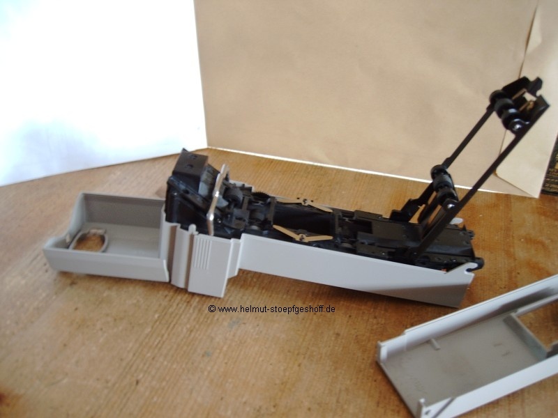 3/ Carefully lever the top roller assembly (the
bridge) from its hinge pin and keep it safe for
later. This “bridge” has an open slit in the hinge-socket which
allows
you to remove it easily from the pin. Note - do not bend the “bridge”
out of
shape or it may not align back to the hinge-pins. 3/ Carefully lever the top roller assembly (the
bridge) from its hinge pin and keep it safe for
later. This “bridge” has an open slit in the hinge-socket which
allows
you to remove it easily from the pin. Note - do not bend the “bridge”
out of
shape or it may not align back to the hinge-pins.
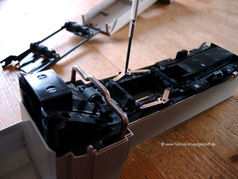
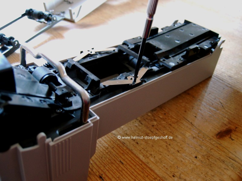 You will need to remove the angled metal strips (pressure springs)
located above and below the scanning hole.
4/ Take the small Philips screwdriver and remove the two black
screws holding them. The pressure springs hold the loading
track in position.
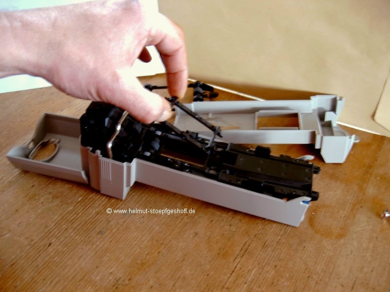 5/
Now
you can remove the loading track. Please look very carefully at
the loading track, at the pins on the right and the left hand side,
which hold the track in place. They are different sizes. This
means
that it only fits in one way. 5/
Now
you can remove the loading track. Please look very carefully at
the loading track, at the pins on the right and the left hand side,
which hold the track in place. They are different sizes. This
means
that it only fits in one way.
Warning!
Underneath the loading track, a light-sensor can be seen (on the side
where the screws are closer together and closer to the opening).
Please do not touch or scratch this sensor! Any damage to this would
mean that the adaptor can no longer position the film strips correctly.
6/ Now, turn the adaptor over, and remove all six screws on the
bottom.
7/ Carefully lift the black assembly out of its grey plastic shell.
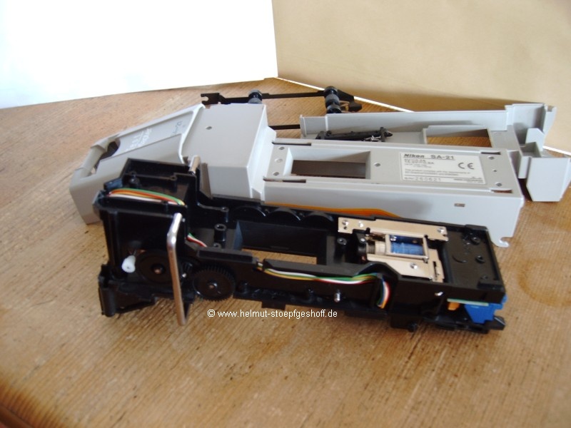 Now
you can see that the locking bar for the top roller bridge is open at
the
bottom. Pivot the bar (as if in roller assembly "open" position), and
lift the bar so both hinge ends come out of their pivoting socket
toward the direction of the smaller end of the adaptor. At the same
time, turn the “bracket” a little so that it can be
released from its tilt limit guides. Now
you can see that the locking bar for the top roller bridge is open at
the
bottom. Pivot the bar (as if in roller assembly "open" position), and
lift the bar so both hinge ends come out of their pivoting socket
toward the direction of the smaller end of the adaptor. At the same
time, turn the “bracket” a little so that it can be
released from its tilt limit guides.
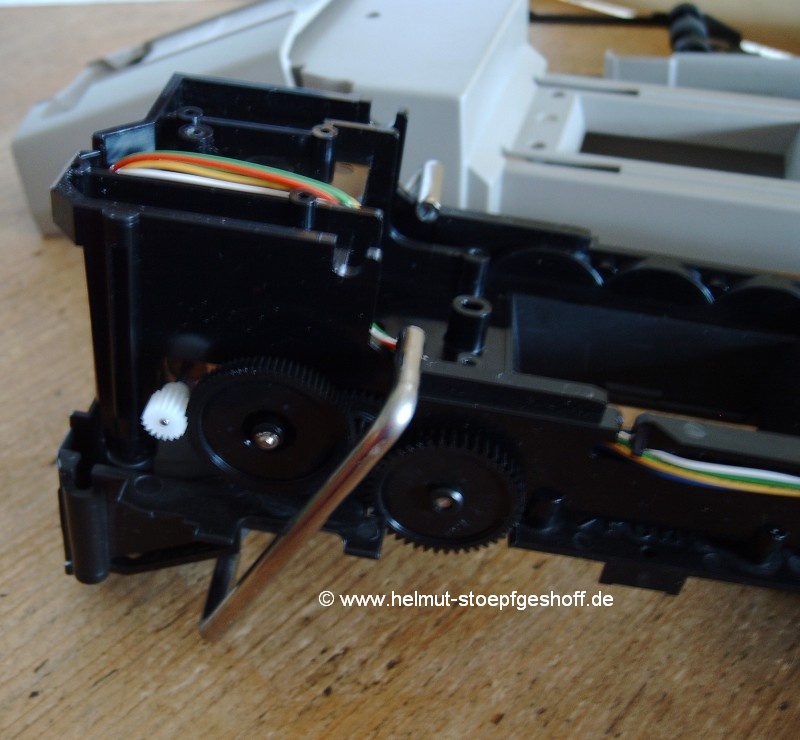 (When reassembling, the orientation of the locking bar
is not important as it is
completely symmetrical. All you will need to remember is that it
is the right way around, has to be loaded firstly into the tilt limit
guides, so that it will then
later fit into its pivot point socket. This is not very
difficult. The “locking bar” does not stay easily into its socket
when the adaptor is turned over when returning to the grey plastic
shell.)
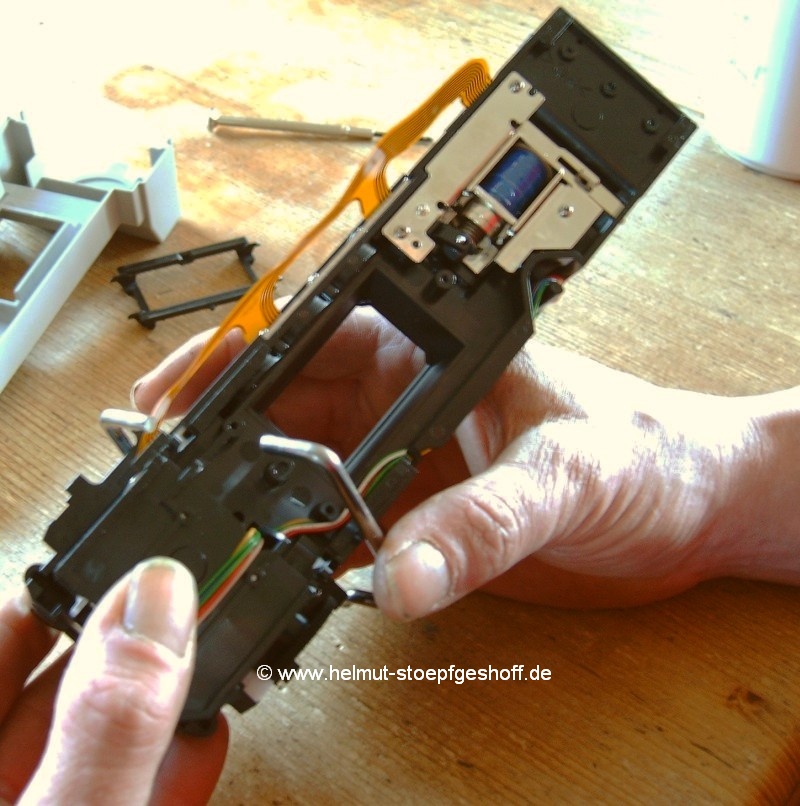
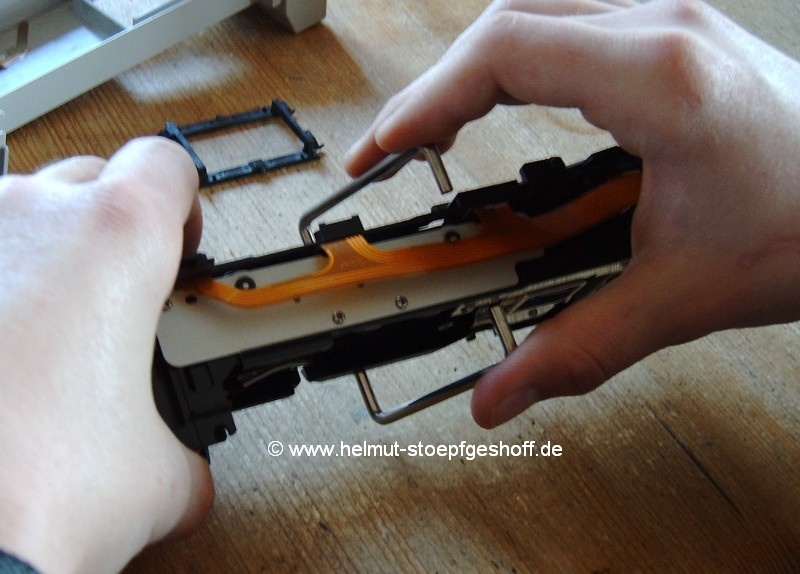
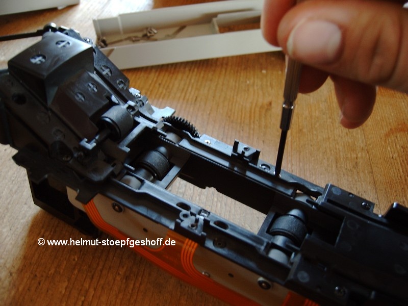
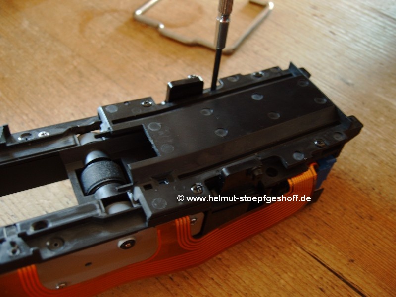
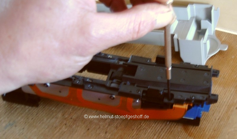
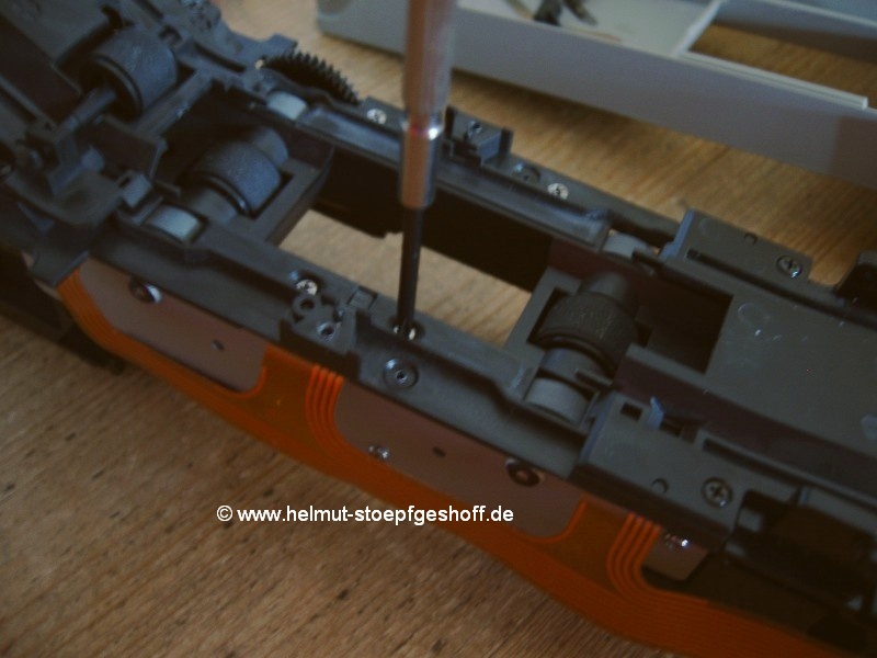
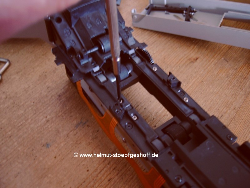
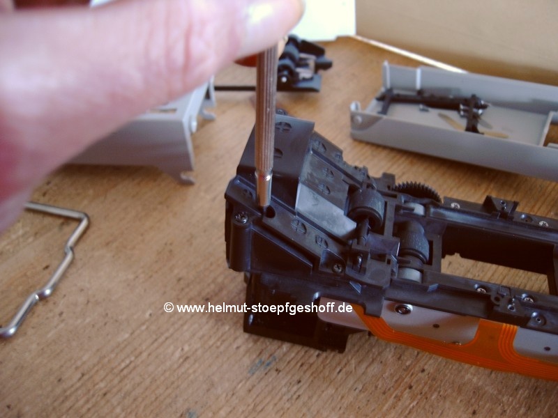
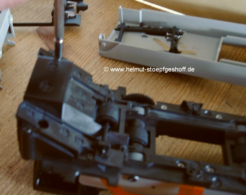 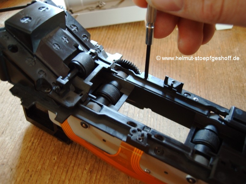 Next, turn over the chassis and remove the eight
screws, as shown in pictures 9-16. Caution! Be especially careful
with the two screws left and right from the light sensor, at the edge
of the scanning
opening (Pictures 14-15). If your screwdriver
slips at this point, there is a good chance that you will destroy your
light sensor! Next, turn over the chassis and remove the eight
screws, as shown in pictures 9-16. Caution! Be especially careful
with the two screws left and right from the light sensor, at the edge
of the scanning
opening (Pictures 14-15). If your screwdriver
slips at this point, there is a good chance that you will destroy your
light sensor!
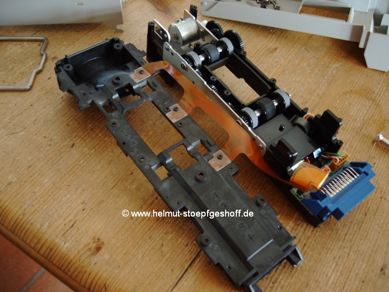 After
all eight screws have been removed, the complete film transport
assembly can
be lifted up, flipped over, and placed next to adaptor chassis. After
all eight screws have been removed, the complete film transport
assembly can
be lifted up, flipped over, and placed next to adaptor chassis.
You can see the three light-sensors which are attached with
a screw to the underside of the film transport assembly, or more
precisely, you can see the flexible printed circuit board which is
soldered to the
light-sensors. You do not need to be overly concerned with this
flexible printed circuit board, as it is very robust. It can be
twisted around without
problem, as long as it is not jerked or folded.
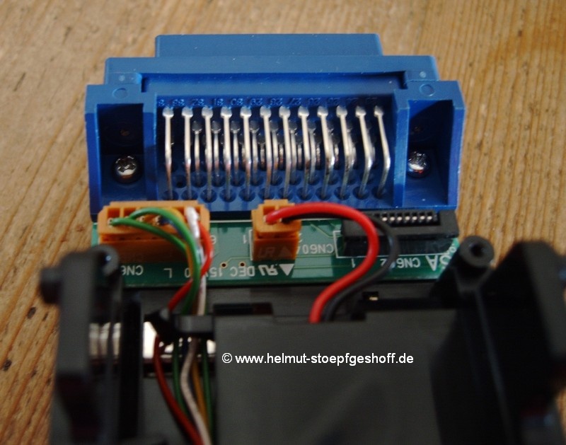 The
plugs that connect the “transport-motor” and the “lock out magnet” to
the hard circuit board should NOT be removed. These plugs are
very
small, and they are barbed very difficult. There is also the
risk of creating hairline fractures in the circuit board. The
plugs that connect the “transport-motor” and the “lock out magnet” to
the hard circuit board should NOT be removed. These plugs are
very
small, and they are barbed very difficult. There is also the
risk of creating hairline fractures in the circuit board.
For the same reasons, the flexible printed circuit board should also
not be unplugged -
the flexible printed circuit board can gently be twisted around as
movement is required.
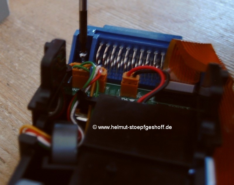 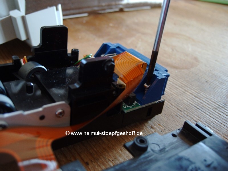 With
the larger Philips screwdriver, unscrew the two screws attaching the
blue
connector block and the hard circuit board to the chassis of the
adaptor. The
blue connector block and the circuit board underneath are joined
together. With
the larger Philips screwdriver, unscrew the two screws attaching the
blue
connector block and the hard circuit board to the chassis of the
adaptor. The
blue connector block and the circuit board underneath are joined
together.
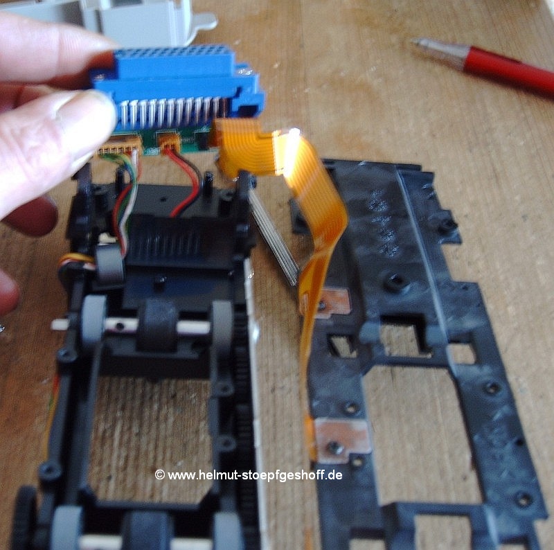 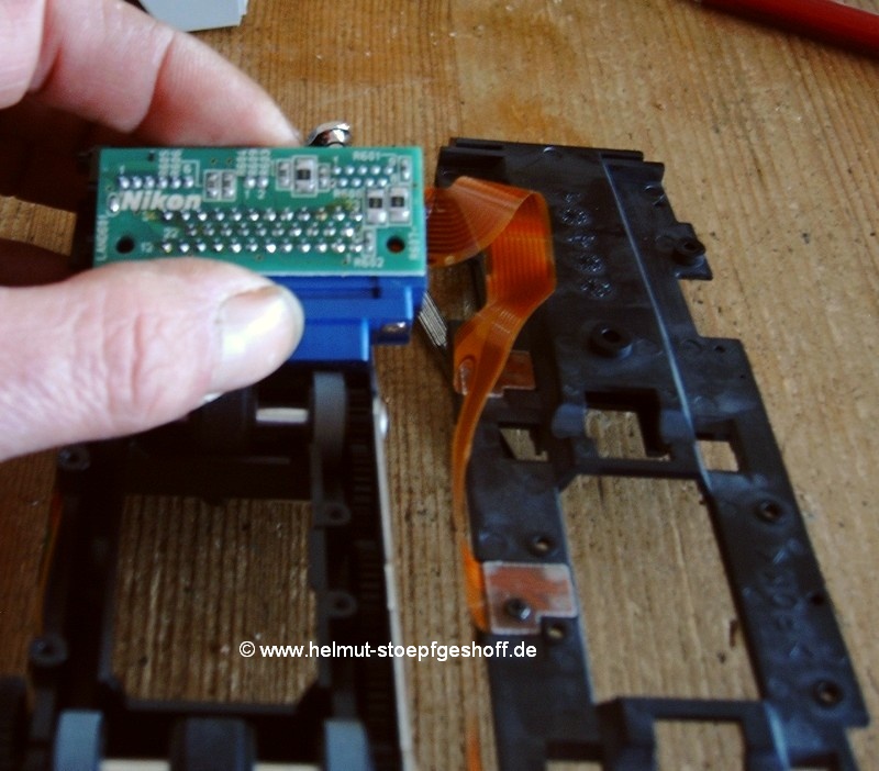 After
this
unit has been removed, unhook the cable which leads to the motor from
the chassis.
The circuit board and blue connector can now be flipped over 180
degrees. The under-side of the hard circuit board is now visible. After
this
unit has been removed, unhook the cable which leads to the motor from
the chassis.
The circuit board and blue connector can now be flipped over 180
degrees. The under-side of the hard circuit board is now visible.
You are now ready to begin the real part of the
modification.
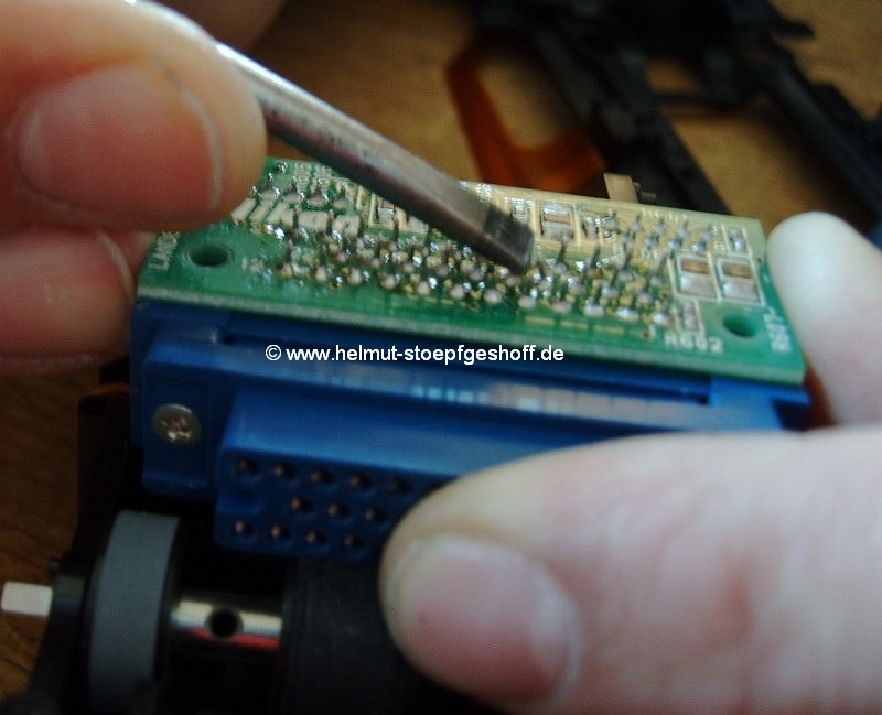 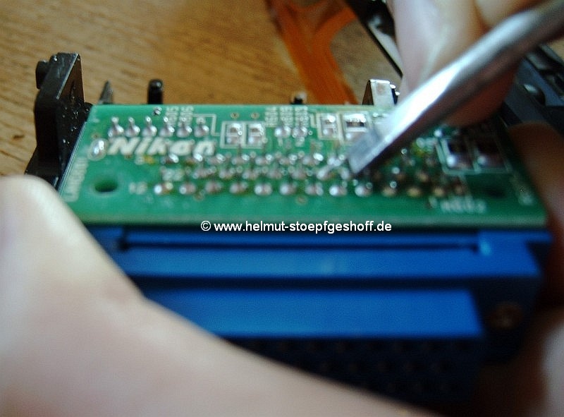 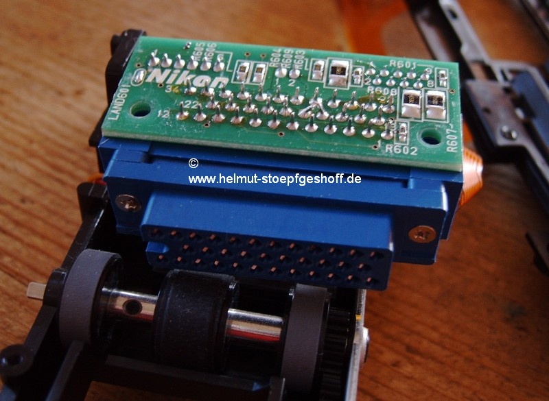 On the
hard circuit board, find the three contact rows which attach the blue
connector. In every row, there is a small number
printed into the circuit board. The contact next to each printed
number indicates the contact number. On the
hard circuit board, find the three contact rows which attach the blue
connector. In every row, there is a small number
printed into the circuit board. The contact next to each printed
number indicates the contact number.
Contacts 16 and 17 have to be joined to each other. With
the blue connector block pointing towards you, these are the fourth
and the fifth contacts from the right hand side in the middle row.
Take the single
slit screwdriver and bend the two contacts ends towards each other, so
that
they touch or almost touch each other.
A little force might be needed, but there is no need to worry about
damage. Be careful that you bend the correct
two contacts, and that the others are not bent. Possible
fractures in the
soldercan be corrected in the next stage.
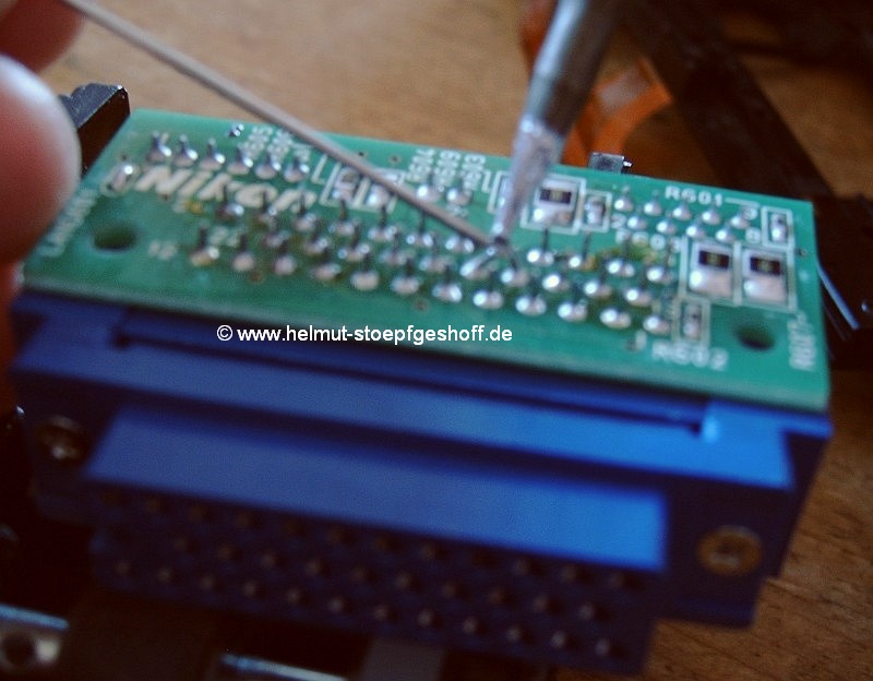 Take your small soldering iron and solder together
only the tips of these two bent contacts. Touch the soldering iron tip
on the
contacts until the solder on the bottom of the contacts become slightly
liquid. At
this point, apply a little more solder to the top of the contacts in
order to form a bridge at the top. Take your small soldering iron and solder together
only the tips of these two bent contacts. Touch the soldering iron tip
on the
contacts until the solder on the bottom of the contacts become slightly
liquid. At
this point, apply a little more solder to the top of the contacts in
order to form a bridge at the top.
Reassemble (remember to take care
with the fragile film sensor, and your flexible circuit board when
sliding the chassis into its grey shell), and there you go!
Your
SA-21 can now fulfill all of the functions of the SA-30 adaptor.
Please continue to read these
instructions,
as they contains further important tips.
Nikon, or myself, would solder the contact bridge in a
different place. I have purposely chosen this solution for users
of this manual, who might not possess the expertise ore
equipment. For more experienced users, however, the originally
designed position is shown in the last picture.
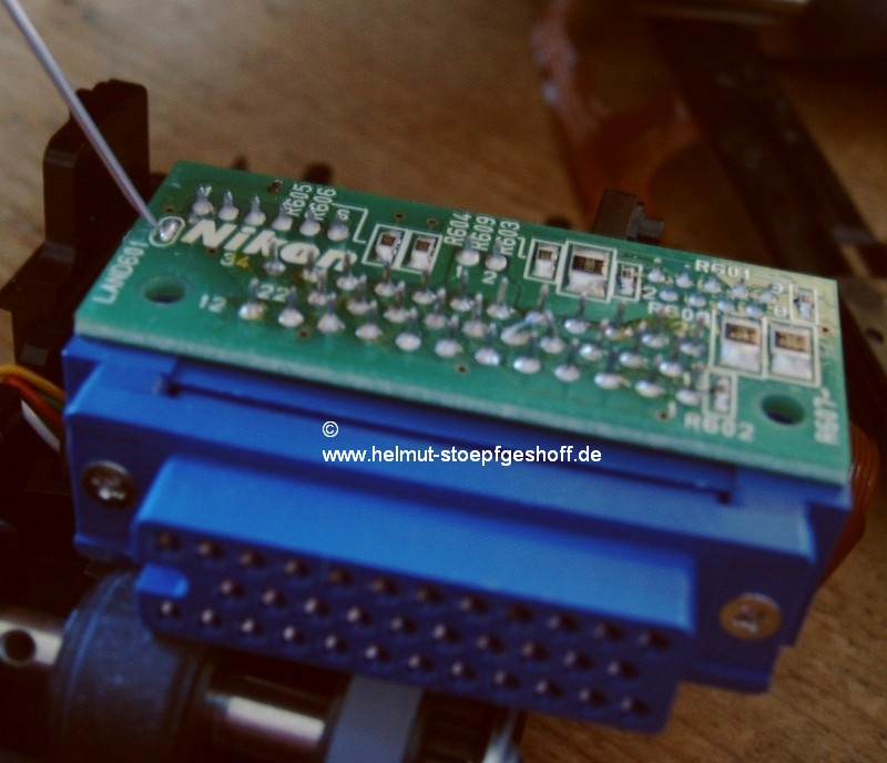 Under
the finished bridge, shown in the
last picture, there are two very small soldering-tracks. Under
the finished bridge, shown in the
last picture, there are two very small soldering-tracks.
Please only solder at this point if
you have both the necessary equipment and experience….
At this point, I would like to explain a little about
the reassembling of the adaptor.
Please do not tighten all screws as tightly as they were
beforehand. The screws were originally tightened by a high speed
machine, which caused them to become quite hot. Because of this
heat, the screws had been slightly melted into their fitting
points.
This explains why they felt so tight to unscrew.
I also recommend thoroughly dusting down all components before putting
the
adaptor back together. Make sure that you only use a very soft
brush or blower when doing this. Be particularly careful when
dusting
the lens of the light-sensors.
There is NO need to oil or lubricate the
moveable components in any way….
Only test your adaptor after it has been
completely reassembled. Even if only the top plate has not
been re-attached, the adaptor will not work well in your scanner…
I hope that your modification has been completely successful, and that
you
can now enjoy the improvements you have made your adaptor.
In concluding, you are welcome to read my Notes
for the safe using
of your modified SA-21 adaptor or have a look on the download site.
If you have any questions, please contact me by
e-mail
But please note that my English isn't good enough for long messages
with
a lot of confusing technical words ;-(

(unclickable for obvious reasons)
special thanks to: Rupert Gillet for the excellent translation at
very short notice, and Lex Mrocki for tecnical cleaning!
Up to
the Top
|
|


 3/ Carefully lever the top roller assembly (the
bridge) from its hinge pin and keep it safe for
later. This “bridge” has an open slit in the hinge-socket which
allows
you to remove it easily from the pin. Note - do not bend the “bridge”
out of
shape or it may not align back to the hinge-pins.
 You will need to remove the angled metal strips (pressure springs)
located above and below the scanning hole.
 5/
Now
you can remove the loading track. Please look very carefully at
the loading track, at the pins on the right and the left hand side,
which hold the track in place. They are different sizes. This
means
that it only fits in one way.
  Now
you can see that the locking bar for the top roller bridge is open at
the
bottom. Pivot the bar (as if in roller assembly "open" position), and
lift the bar so both hinge ends come out of their pivoting socket
toward the direction of the smaller end of the adaptor. At the same
time, turn the “bracket” a little so that it can be
released from its tilt limit guides.


 Next, turn over the chassis and remove the eight
screws, as shown in pictures 9-16. Caution! Be especially careful
with the two screws left and right from the light sensor, at the edge
of the scanning
opening (Pictures 14-15). If your screwdriver
slips at this point, there is a good chance that you will destroy your
light sensor!


 After
all eight screws have been removed, the complete film transport
assembly can
be lifted up, flipped over, and placed next to adaptor chassis.
 The
plugs that connect the “transport-motor” and the “lock out magnet” to
the hard circuit board should NOT be removed. These plugs are
very
small, and they are barbed very difficult. There is also the
risk of creating hairline fractures in the circuit board.
 With
the larger Philips screwdriver, unscrew the two screws attaching the
blue
connector block and the hard circuit board to the chassis of the
adaptor. The
blue connector block and the circuit board underneath are joined
together.
 After
this
unit has been removed, unhook the cable which leads to the motor from
the chassis.
The circuit board and blue connector can now be flipped over 180
degrees. The under-side of the hard circuit board is now visible.

 On the
hard circuit board, find the three contact rows which attach the blue
connector. In every row, there is a small number
printed into the circuit board. The contact next to each printed
number indicates the contact number.
 Take your small soldering iron and solder together
only the tips of these two bent contacts. Touch the soldering iron tip
on the
contacts until the solder on the bottom of the contacts become slightly
liquid. At
this point, apply a little more solder to the top of the contacts in
order to form a bridge at the top.
 Under
the finished bridge, shown in the
last picture, there are two very small soldering-tracks.